
I’ve written a couple of posts about the BGT-project which I’m working on lately. A recurrent topic, when speaking about the BGT, is: “where should the border polygon be situated ?”
Frist suggestion is the cadastral border. This is also an authentic registration and a good solution for two municiplalities. I’m involved with a project at one of the provinces and they “slice” through municipalities with their provincial roads, that makes the cadastral border less useful.
 Users of the provincial map are among others the departments of road- and greenmanagement. Besides surveying the topography, that is situated in a corridor along the road, the road- and greenobjects are important for these maintenance maps. Sometimes there is more green managed than is owned by the province – imagine a ditch that is mown completely, while the cadastral borderline is in the center of the ditch. Currently many road crossings are tranferred into roundabouts, and therefore the province needs to buy pieces of land from municipalities or private owners. The new cadastral situation will take some time to become established and therefore the cadastral border isn’t up-to-date.
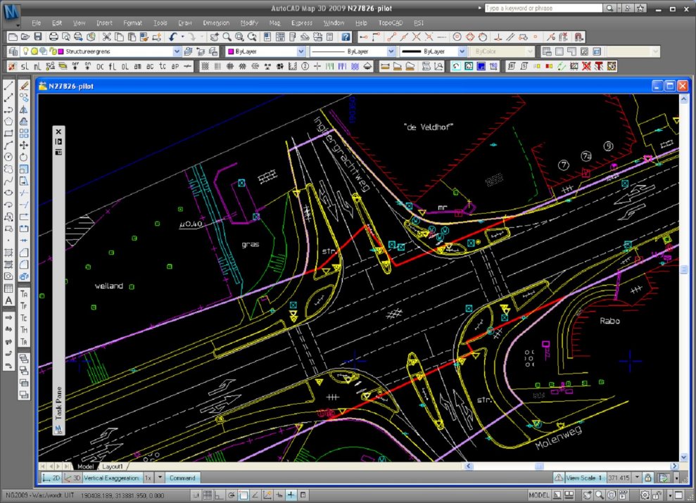
 In our project we’ve taken a pragmatic approach: we use the outside topographic lines in the corridor maps to build the polygons. In some cases we have to add supporting-lines to close the polygons. If the BGT border polygon has been defined than we will know which polygons needs to be splitted. The current maintenance and cadastral borders are left out of the proces for now. Also buildings, fences, roadlines that a partly on the map, but outside the provincial maintenance area are left out of polygon creation.
With this approach we can create the object oriented map and use the geometry of road- and greenobjects to connect to maintenance-data.
In the meantime still discussing with the GBKN Foundation, municipalities, waterboards, National Road Administration and the Ministry of Housing, Spatial Planning and the Environment about the BGT border polygon.

 First we’ve created the centroids, AutoCAD points with attribute information in conformity with the IMGeo-model.