Draw pipes as smart CAD-objects?
Yes you can!
A while ago an implementation of vdPCADdesign for entering revision drawings for sewer-house connections was delivered. Main sewer functionality has recently been added.
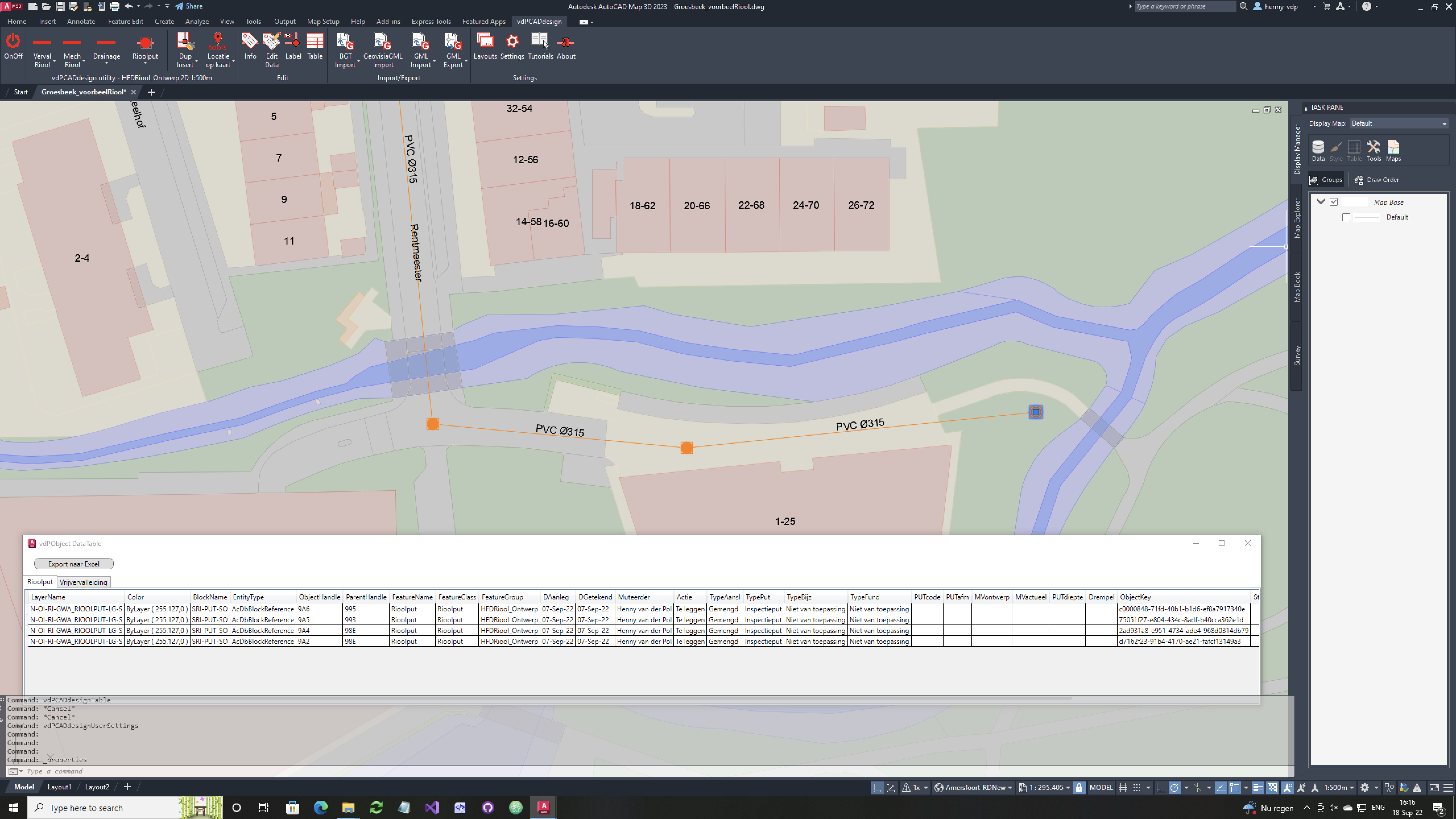
The starting point is to increase the main sewerage system in AutoCAD with which design/revision drawings can be made. The AutoCAD polylines and blocks are provided with additional information allowing an export to GML-files. These files form input for the BOR system in which, among other things. the sewage system of the entire municipality is managed.
When adding new sewer features, the properties must first be entered/selected in accordance with the datamodel, some of which are mandatory. Then the user can – as usual with a polyline – create the geometry. When closing the polyline, the pipe is drawn, on the correct NLCS-layer, with color and linetype. The Xdata-information is linked to it and a label is created. These labels “stick” to the pipes and when the location of the pipe is adjusted with regular AutoCAD functionality; grip edit, insert vertex etc. the labels are also adjusted.
vdPCADdesign is a C#.NET utility and available for various AutoCAD-versions.
More information?
Ask the cadgis-consultant or read vdPCADdesign articles on our weblog.

